Open DIY Concept · Build Guide

DIY Dissolving Station

The affordable 30-liter washing station for water- and alkali-soluble 3D printing support structures. Built from a few standard off-the-shelf parts and 3D-printed drive mechanisms.

  • Under €200 total cost through a smart combination of a wake-up pot & 3D printing
  • Active pool circulation through automatic forward and backward rotation
  • 9 clearly defined installation steps in 3 logical assembly phases
Open DIY Hardware< €200 target cost
DIY Dissolving Station
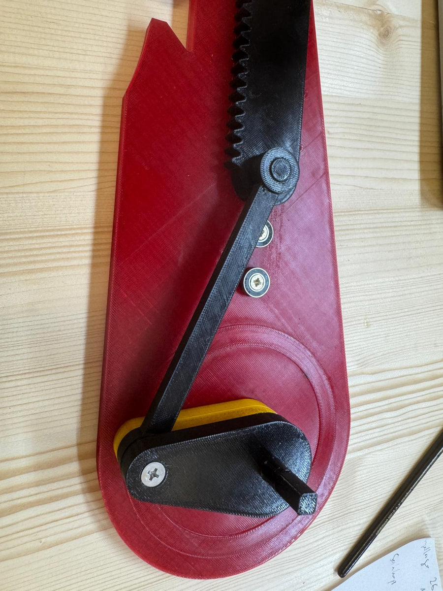
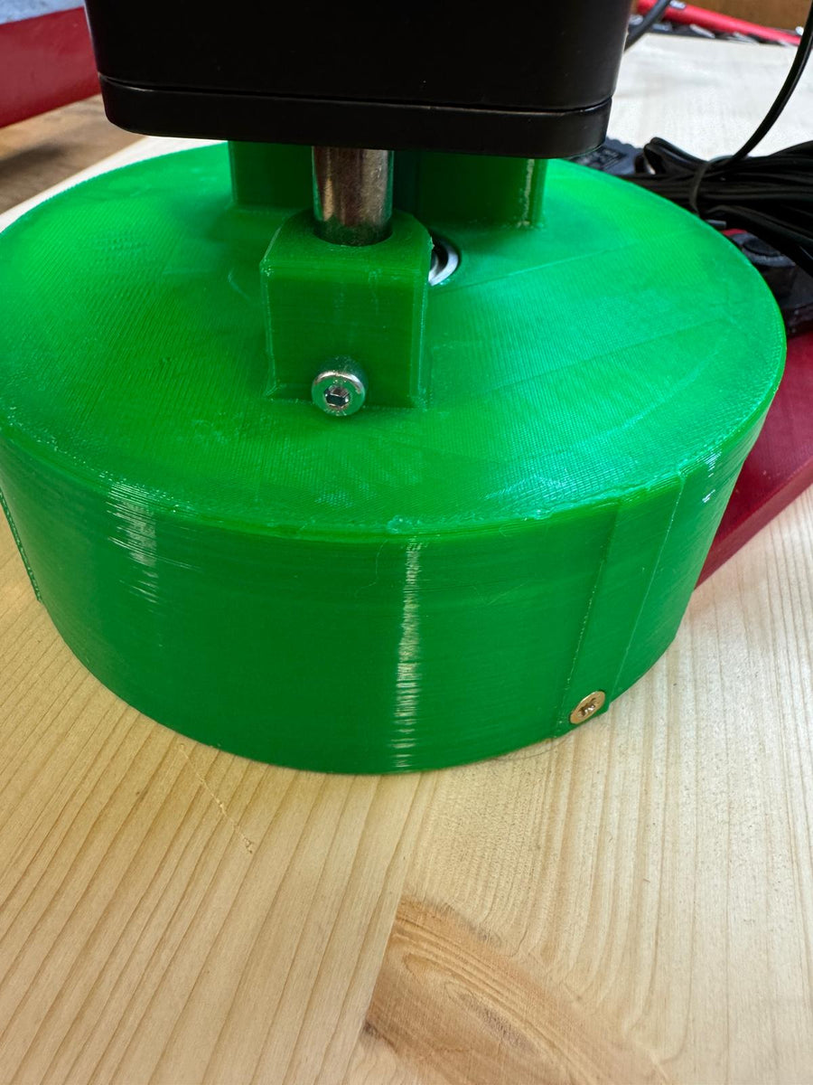
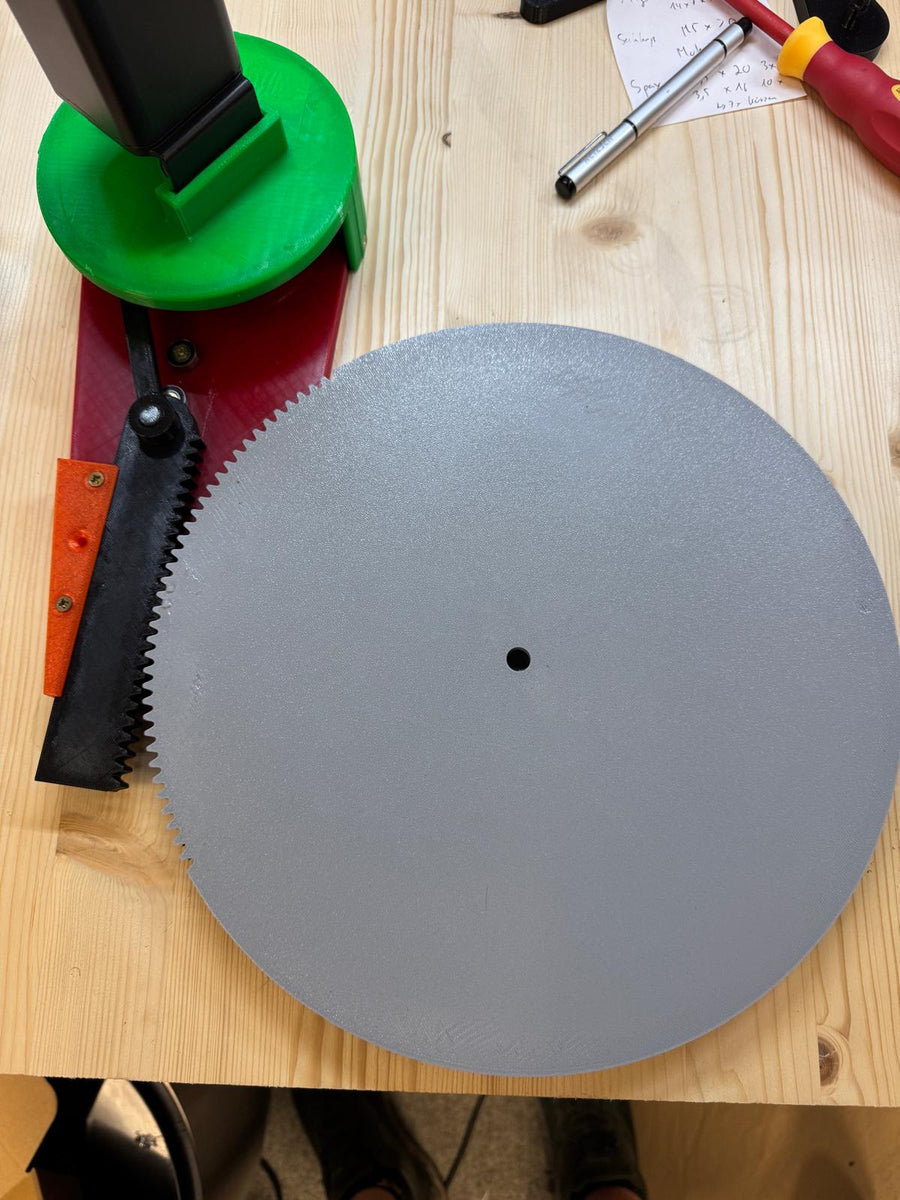
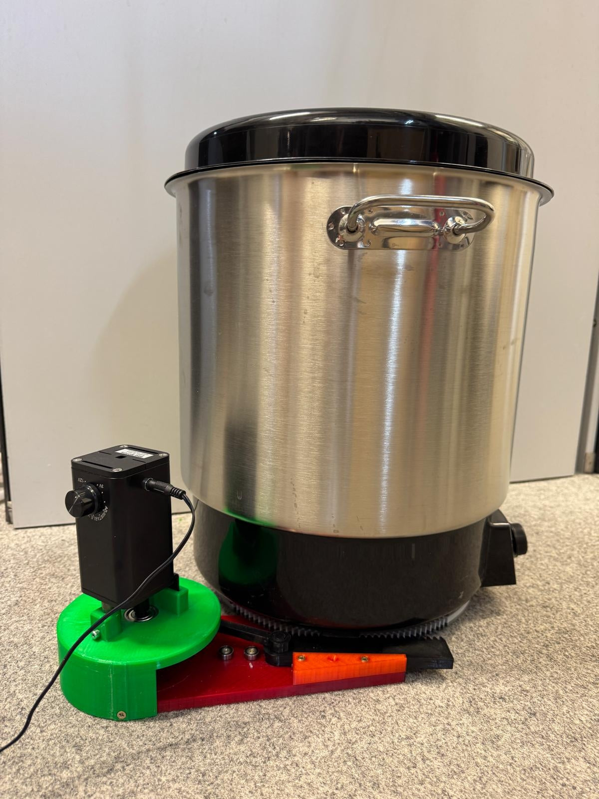
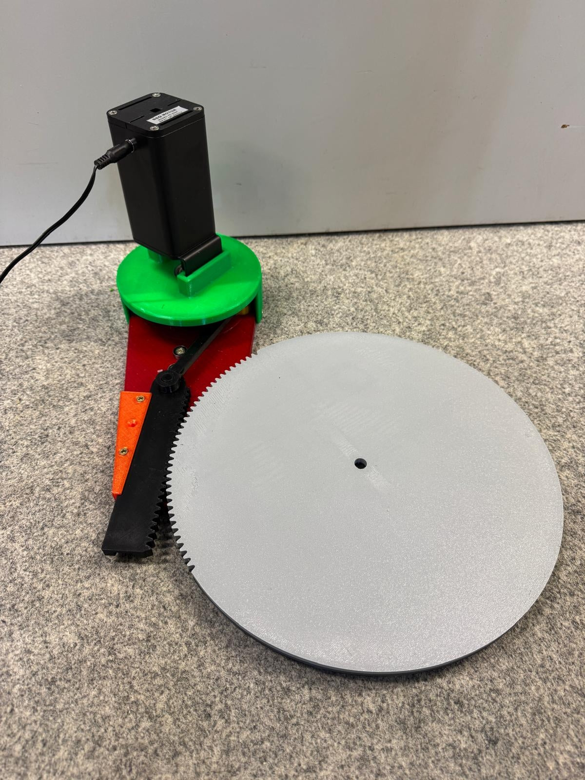
Fully assembled drive unit with toothed turntable and crank mechanism

Operating principle & key data

Simple mechanics.
Continuous movement.

Instead of expensive industrial pumps, the station uses a robust kinematic chain: The uniform rotation of the grill motor is converted via a crank drive, connecting rod, and ball-bearing rack into a gentle, oscillating rotational movement of the 30-liter stainless steel container.

< €200Material & Target Costs
30 litersStainless steel container (Weck WAT24)
30–100 °CAdjustable temperature range
3–12 V DCVariable grill motor (13–56 rpm)
Grill motor (Rotation)Crank & Connecting RodRack and pinion (linear)Turntable & Pot (Oscillation)
Simple mechanics.
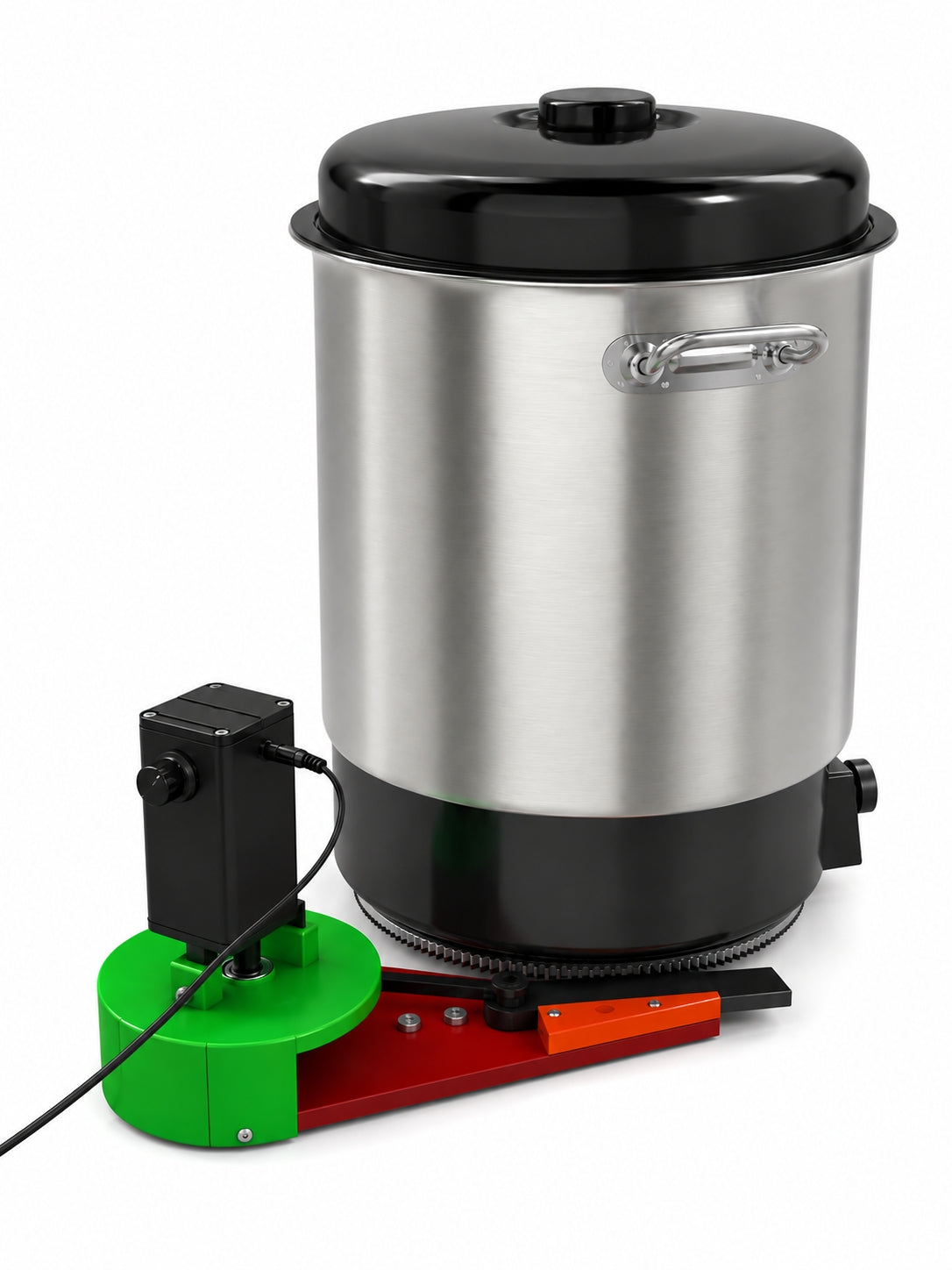
Overall kinematic overview: drive + turntable + 30L heating vessel

Preparation & Bill of Materials (BOM)

Buy. Print. Prepare.

All required components are already linked here to their respective assembly step to prevent confusion over screw lengths and bearing types during assembly.

1. Purchased Parts & Standard Parts

10 items
Main Components & Drive
  • ✓ Weck WAT24 stainless steel preserving pot (30 L, 1,800 W) Finish
  • ✓ Grill motor (3–12 V, 13–56 rpm, 15 W) Step 08
  • ✓ Photo turntable (Ø 200 mm) Step 09
Ball Bearings & Lubrication
  • ✓ 7 × ball bearings 687 (7 × 14 × 5 mm, for rack guidance) Step 01
  • ✓ 2 × ball bearings 6200 (10 × 30 × 9 mm, for crank drive) Step 03 & 07
  • ✓ Lubricating grease (for rack and sliding guide) Step 02
Screws & Fasteners (pay attention to lengths!)
  • ✓ 7 × screw 3.5 × 16 mm (SHORTENED) – shorten by 1–2 mm in advance! Before start + Step 01
  • ✓ 3 × screw 3.5 × 16 mm (ORIGINAL) – leave unshortened Step 07
  • ✓ 3 × screw 3.5 × 20 mm (for side guidance) Step 06
  • ✓ 1 × countersunk screw M5 × 30 mm + 1 × M5 nut Step 04
  • ✓ 1 × screw M4 × 12 mm (for motor mounting) Step 08

2. 3D-printed components

6 assemblies
  • ✓ Base plate (base for guide bearing & drive) Step 01
  • ✓ Rack and side guide Step 02 & 06
  • ✓ Crank and connecting rod components Step 03–05
  • ✓ Motor mount and cover Step 07–08
  • ✓ Gear ring / turntable component Step 09
  • ✓ Centering for the turntable (pot mount) Step 09

Note on printing parameters: Determine material selection (recommended: temperature- and moisture-resistant filament such as PETG, PCTG, or ASA), wall thicknesses, infill, and part orientation based on the original 3D files.

3. Recommended Tool

Mise en place
  • ✓ Screwdriver (suitable for 3.5 mm screws as well as M4 / M5)
  • ✓ Hacksaw / bolt cutters & file (for trimming & deburring the 7 screws for step 01)
  • ✓ Vise or press-fit aid (for pressing the 6200 bearings in straight in step 03 & 07)

Important preparation before starting assembly (Step 00)

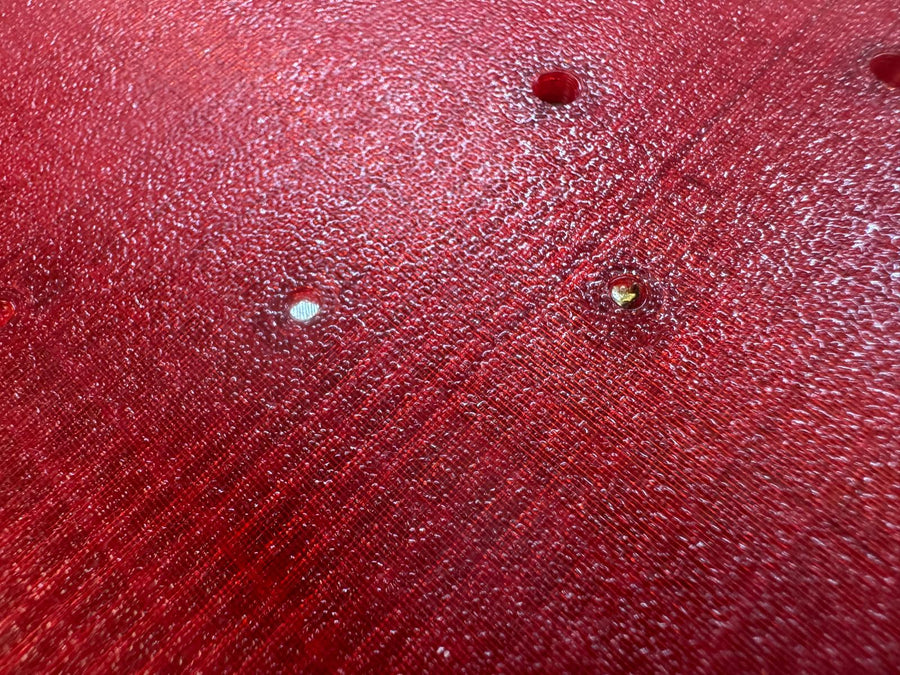
Of the 10 screws (3.5 × 16 mm) in total, exactly 7 must be shortened by 1–2 mm beforehand (to approx. 14–15 mm) and lightly deburred at the tip. Otherwise, the screw tips will push through the base plate in step 01. The remaining 3 screws (3.5 × 16 mm) remain at their original length for step 07.

Assembly Guide · 9 Steps

Step-by-Step Assembly

Each work step first shows the required components, then guides you chronologically through the steps, and concludes with a brief functional check. (Tip: Click on a photo to open the full-screen view.)

Phase I

Assemble base plate & linear guide

Steps 01 – 02
01
Phase I · Linear Guide

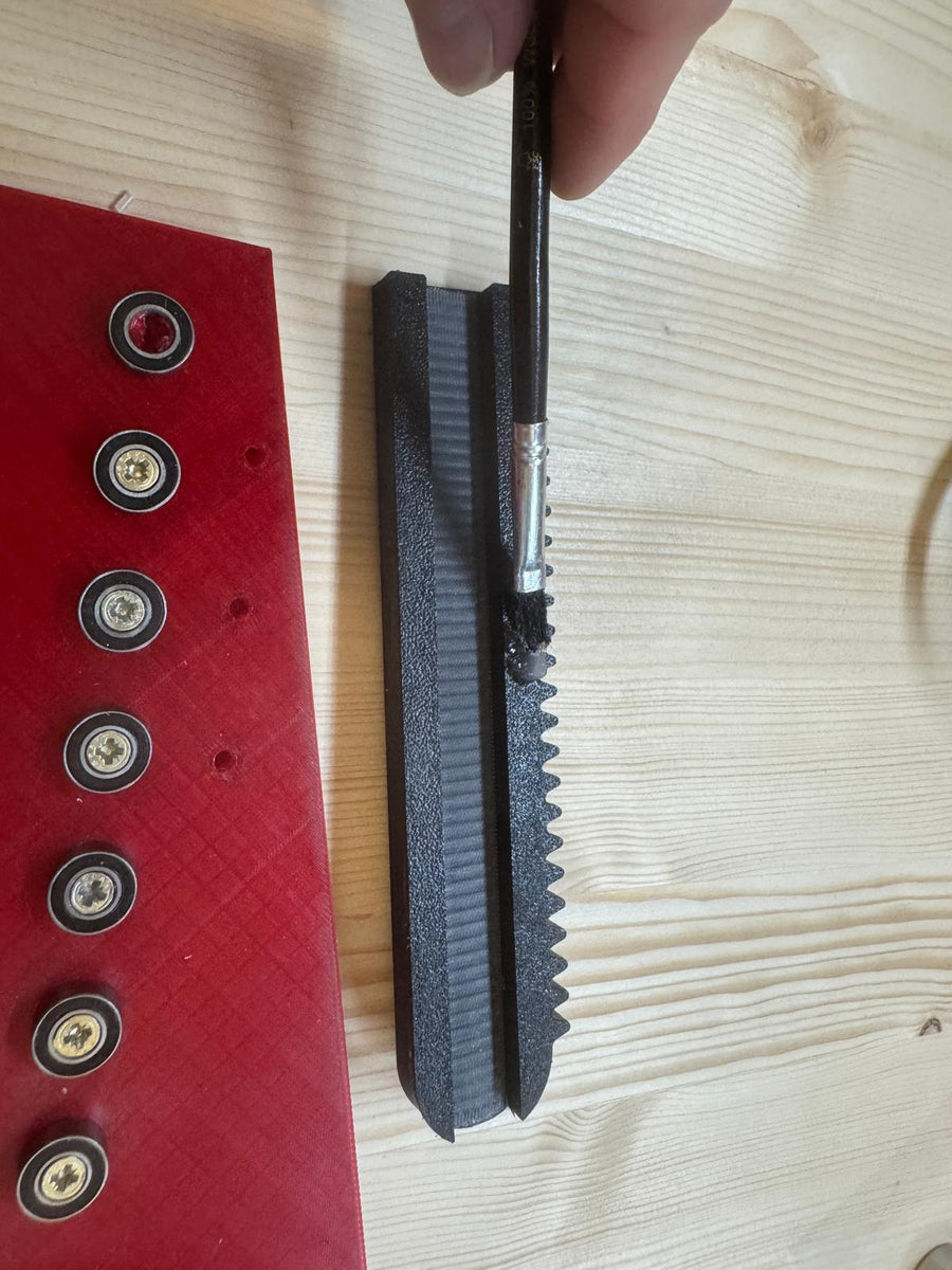
Mount guide bearing on base plate

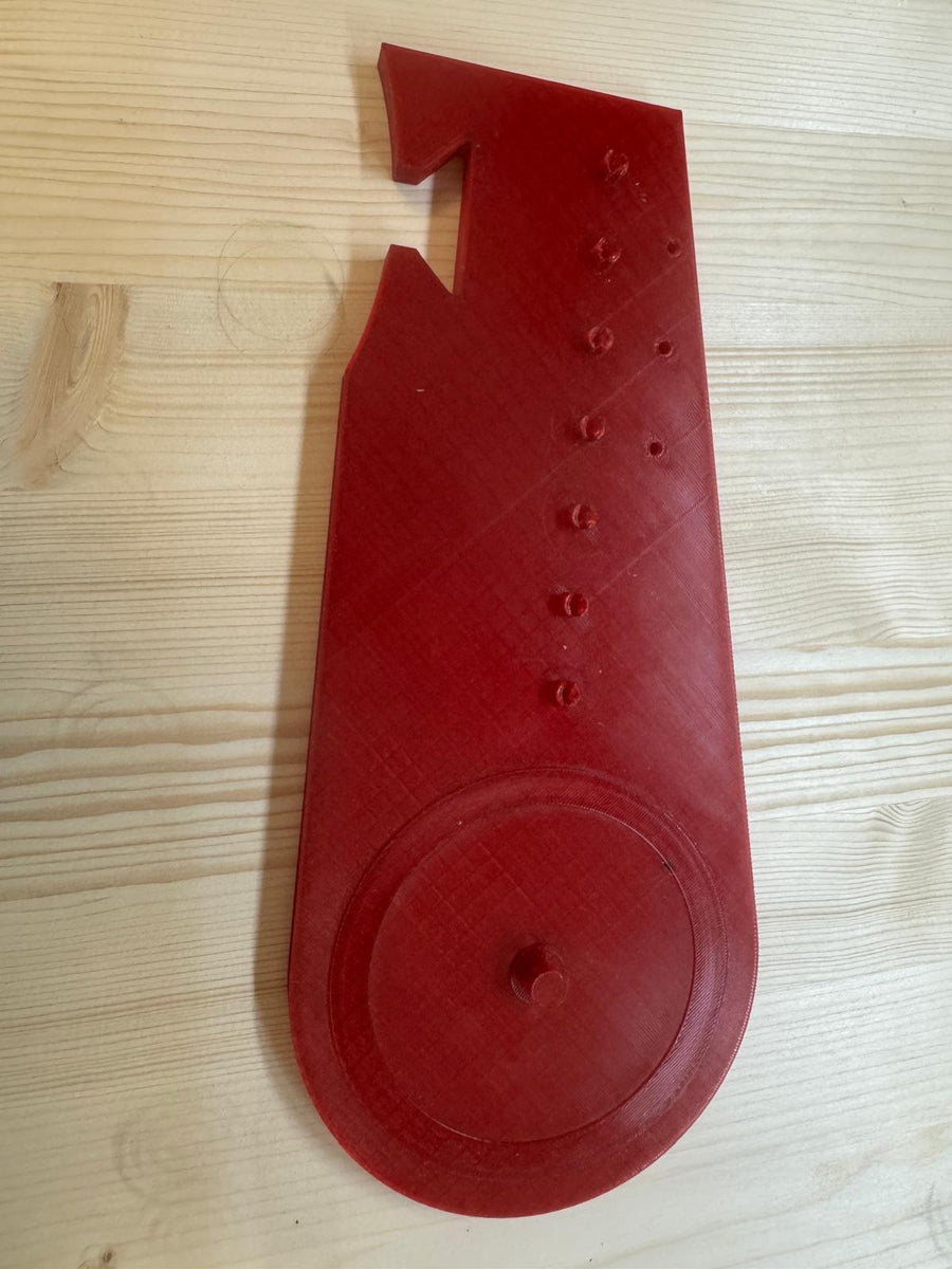
1× base plate (printed part)7× ball bearings 687 (7×14×5 mm)7× screws 3.5×16 mm (shortened by 1–2 mm!)

Caution before screwing in: Use only the 7 screws previously shortened by 1–2 mm (3.5 × 16 mm)!

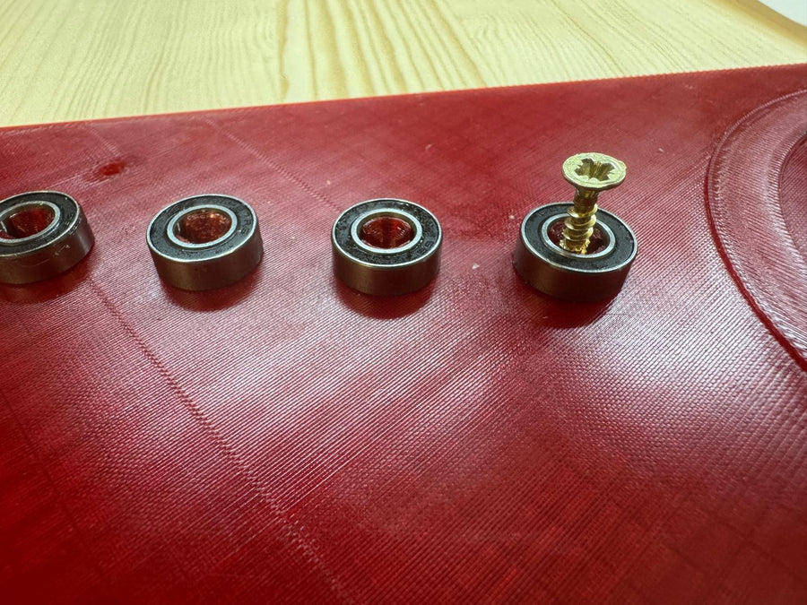
  1. 1Check screws: Ensure that the 7 screws (3.5 × 16 mm) have been shortened by 1–2 mm as shown in Figures 1.1–1.3.
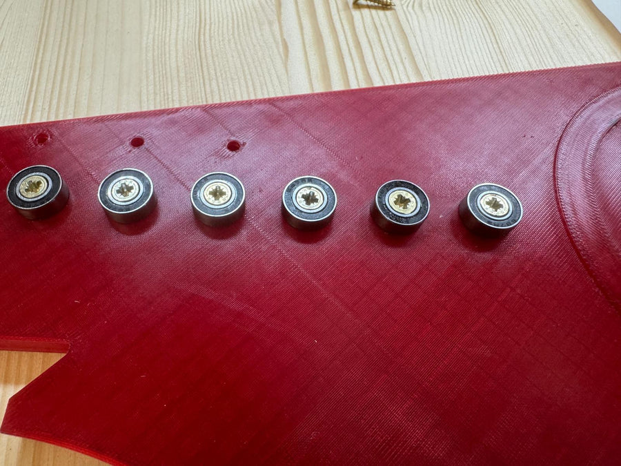
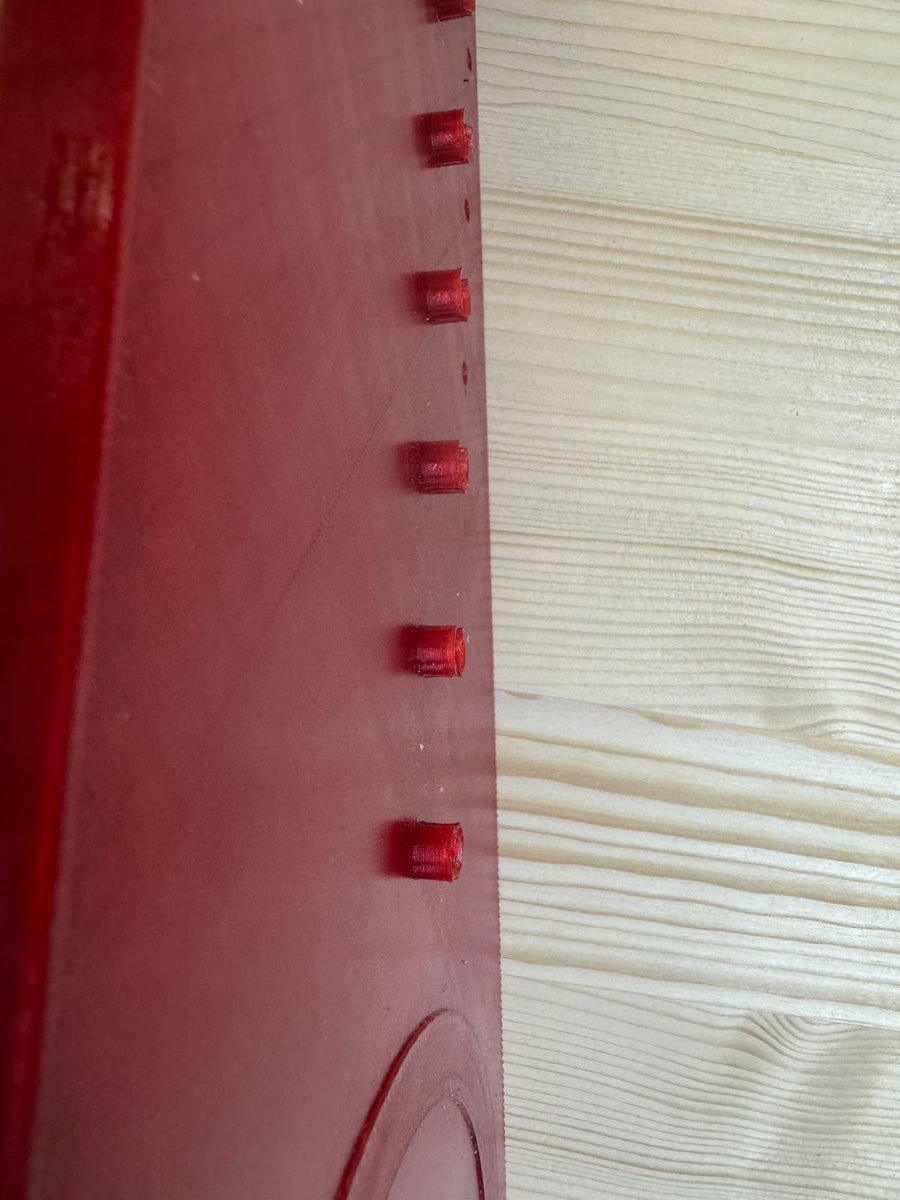
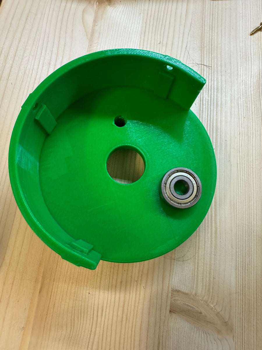
  2. 2Install ball bearings: Place all seven 687 ball bearings (7 × 14 × 5 mm) onto the designated bearing bosses on the base plate (Figure 1.4).
  3. 3Secure bearings: Fasten each ball bearing with a shortened screw (Figure 1.5). Tighten only until the outer rings of the bearings can still rotate freely.
✓ Verification check: All 7 ball bearings sit flush in their seats and rotate easily by hand.
02
Phase I · Linear Guide

Grease the rack and slide it in

1× rack & guide (pressed parts)A little grease
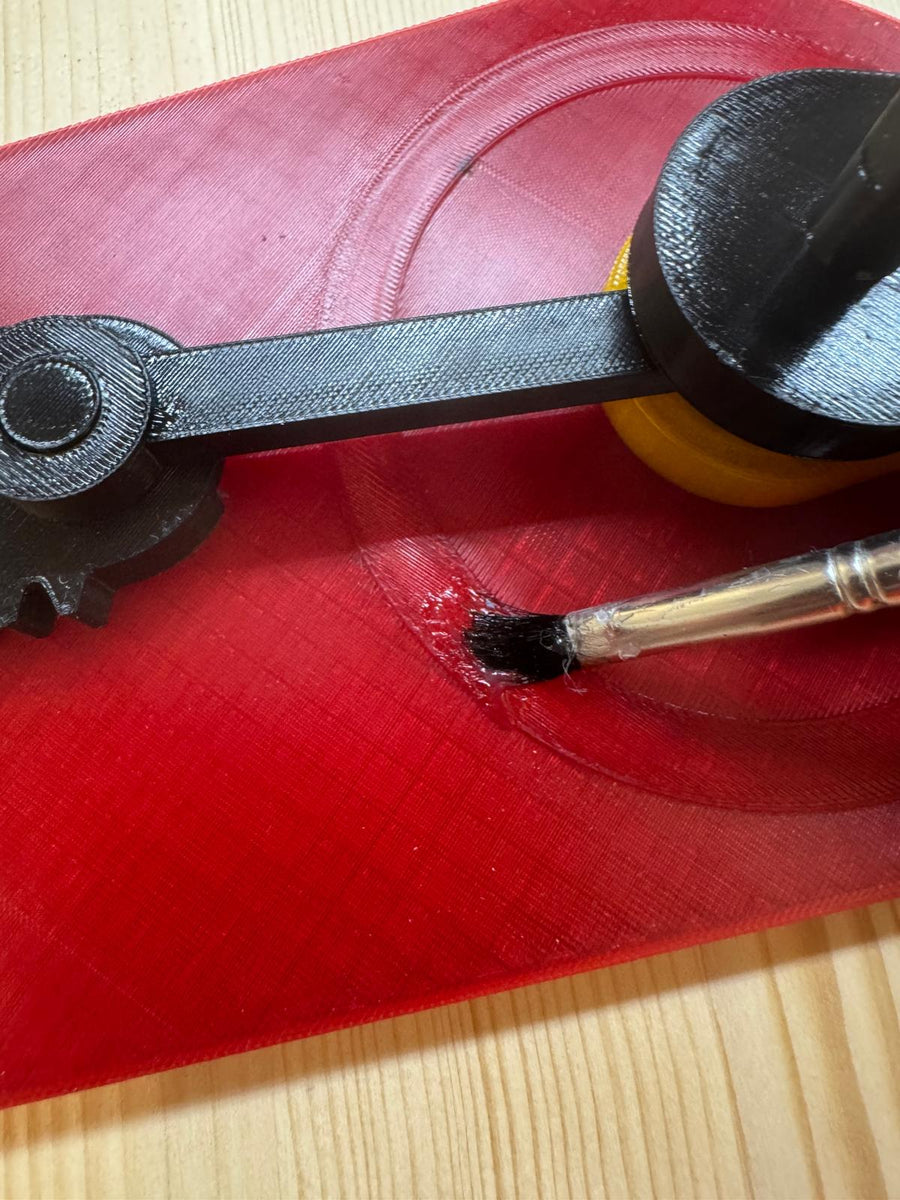
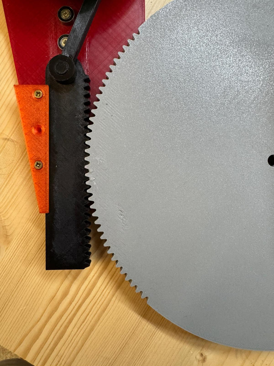
  1. 1Lubricate sliding surfaces: Apply a thin film of lubricant to the guide groove and the teeth of the rack (Figure 2.1).
  2. 2Insert rack: Slide the rack into the guide component (Figure 2.2) and move it several times over the entire stroke to distribute the lubricant evenly.
✓ Verification check: The rack slides smoothly and without resistance in the guide along its entire length.
Phase II

Install crankshaft drive, connecting rod & bearing assemblies

Steps 03 – 07
03
Phase II · Crankshaft Drive

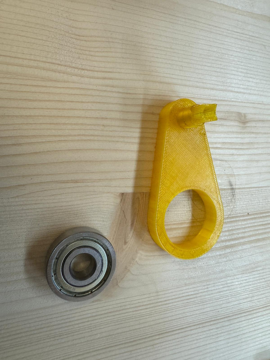
Press in the first 6200 ball bearing

1× ball bearing 6200 (10×30×9 mm)Crank press parts (bearing seat & pin)
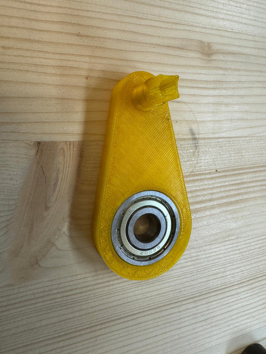
  1. 1Prepare components: Prepare the first large 6200 ball bearing (10 × 30 × 9 mm) and the associated crank press parts as shown in Figures 3.1–3.2.
  2. 2Position the bearing straight: Position the 6200 bearing squarely in the bearing seat of the press part and press it in flush (Figures 3.3–3.4).
  3. 3Insert shaft/crank part: Insert the mating part into the inner ring of the ball bearing as shown in Figure 3.5.
✓ Verification check: The 6200 bearing sits completely flush in the plastic housing; the inserted pin rotates without play.
04
Phase II · Crank Drive

Screw in M5 crank pin

1× M5×30 mm countersunk screw1× M5 hex nutConnecting rod/crank mount
  1. 1Insert M5 nut: Press the M5 nut into the hexagonal recess of the printed part so that it is secured against turning (Figure 4.1).
  2. 2Secure components: Insert the M5 × 30 mm countersunk screw and tighten it in the M5 nut (Figure 4.2).
✓ Verification check: The countersunk head sits flush, and the M5 connection securely holds the crank components together.
05
Phase II · Crankshaft Drive

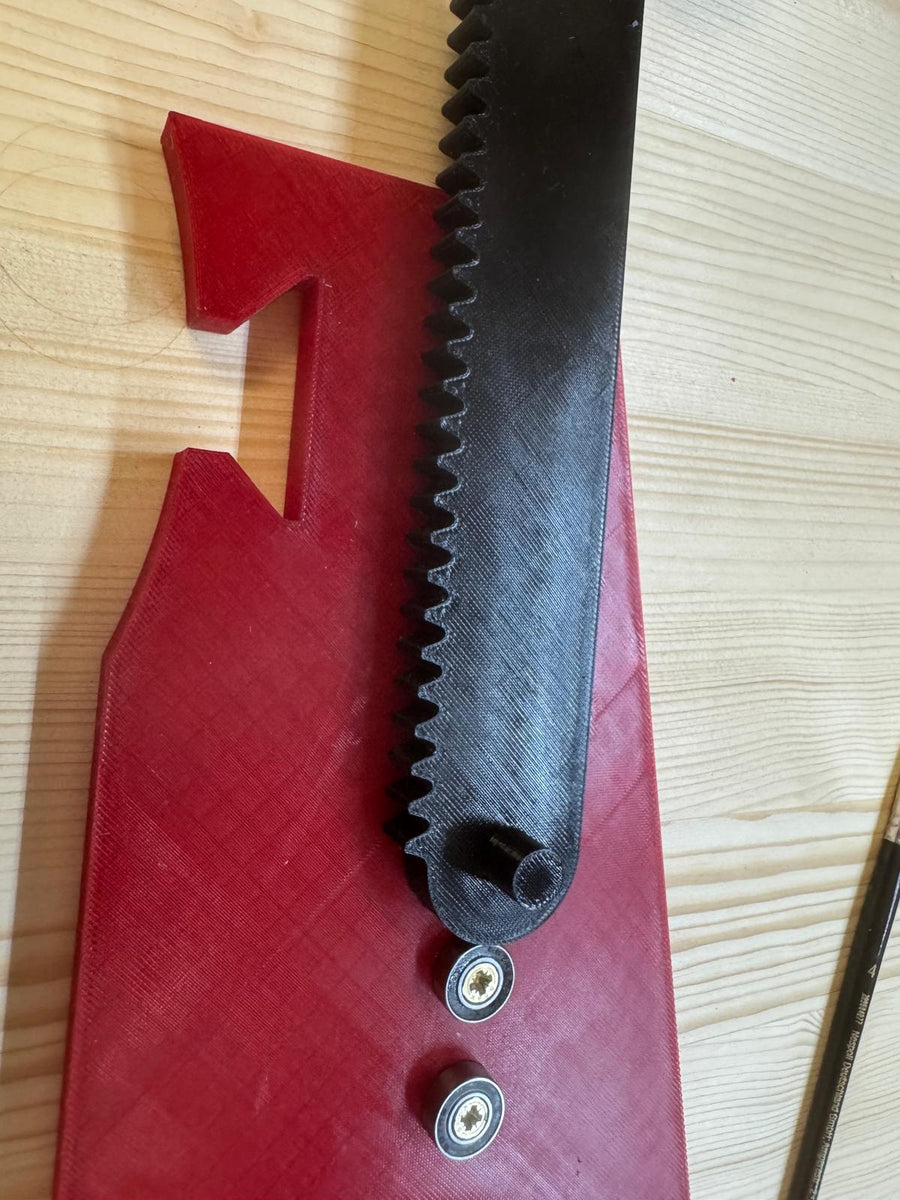
Couple the connecting rod with the rack

Pre-assembled crank/pitman assemblyrack and pinion assembly on base plate
  1. 1Position the assemblies: Align the rack with its guide along the 7 ball bearings on the base plate.
  2. 2Hook up the connecting rod: Connect the pre-assembled connecting rod and crank parts to the pivot point of the rack as shown in Figure 5.1.
✓ Verification check: When the crank is turned by hand, the connecting rod already pushes the rack linearly back and forth between the bearings.
06
Phase II · Crankshaft Drive

Secure the side guide to the base plate

3× screw 3.5×20 mmSide guide on base plate
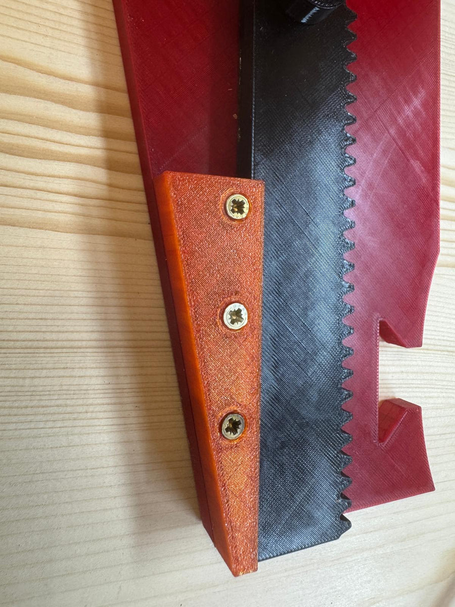
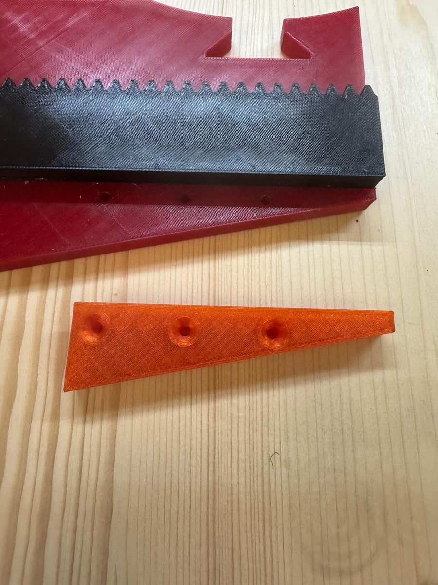
  1. 1Select screw length: Prepare the three longer screws (3.5 × 20 mm) (Figure 6.1).
  2. 2Secure the guide: Screw the side guide firmly to the base plate at the three mounting points (Figure 6.2).
✓ Verification check: The guide sits freely on the base plate; the rack continues to move smoothly.
07
Phase II · Crank Drive

Install the second bearing housing assembly (engine mount)

1× ball bearing 6200 (10×30×9 mm)3× screw 3.5×16 mm (unsheathed!)Motor mount housing (printed part)
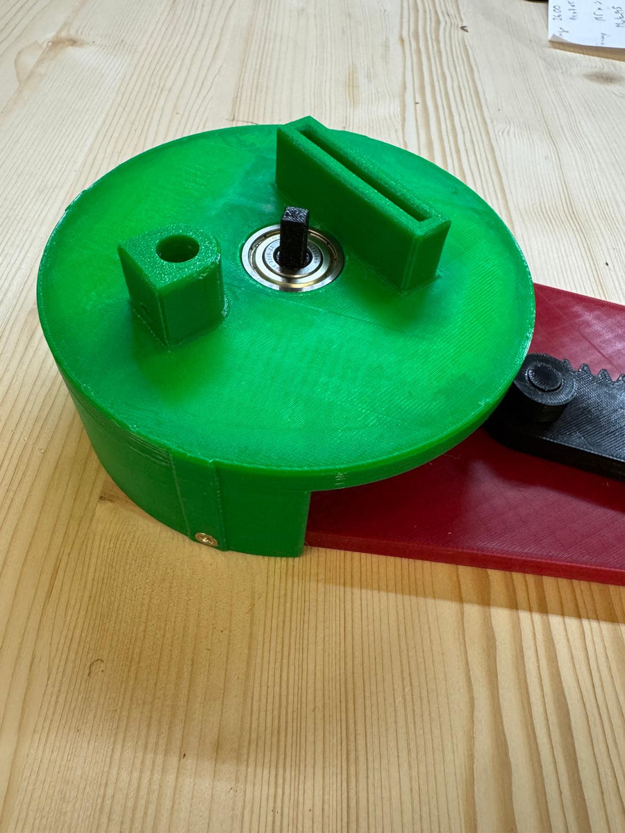
  1. 1Insert the second 6200 bearing: Press the second 6200 ball bearing (10 × 30 × 9 mm) flush into the motor mount (Figure 7.1).
  2. 2Position & screw on the mount: Position the housing over the crankshaft (Figure 7.2) and screw it on with the remaining three unshortened screws (3.5 × 16 mm) (Figure 7.3).
✓ Verification check: The crank drive is now securely supported on both sides by the two 6200 ball bearings.
Phase III

Motor, Turntable & Finish

Steps 08 – 09
08
Phase III · Propulsion

Insert and secure the grill motor

1× Grill motor (3–12 V)1× M4×12 mm screw
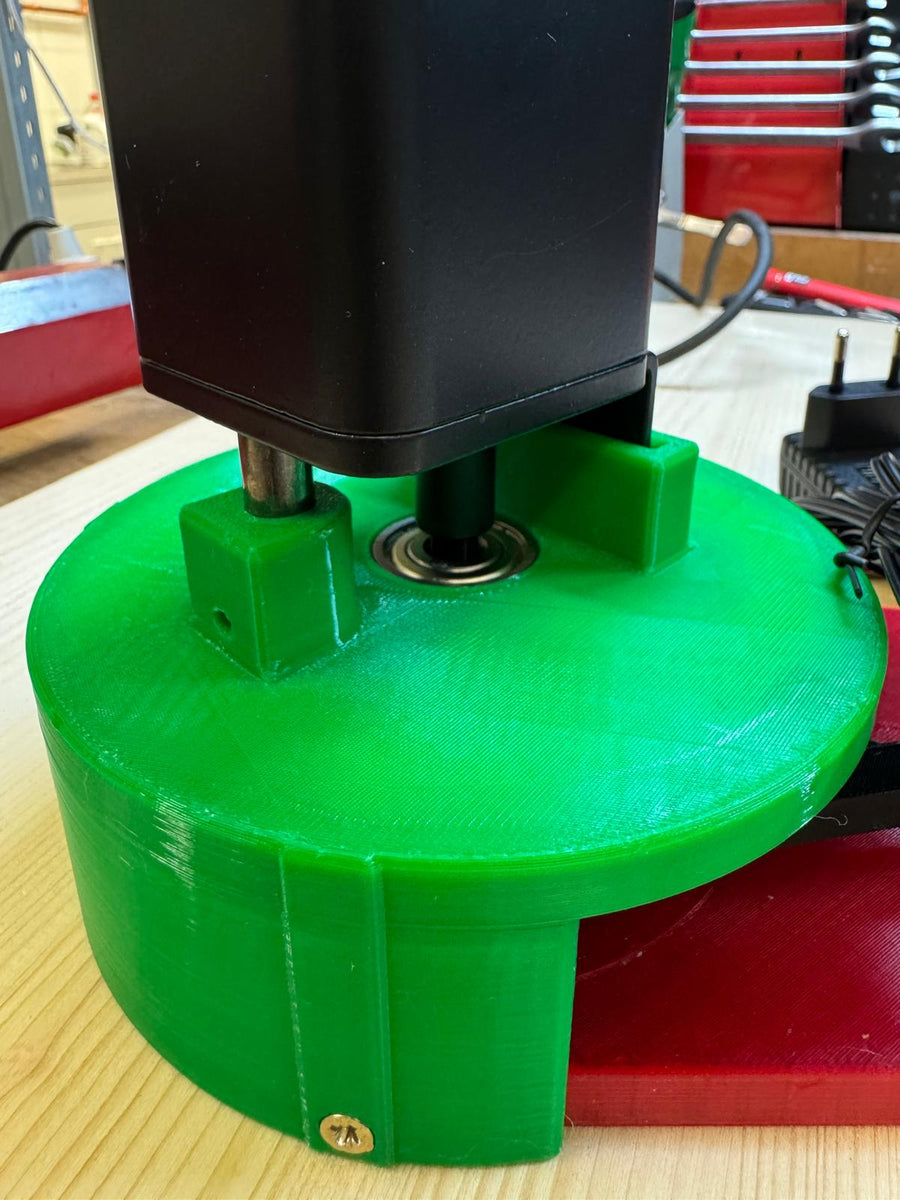
  1. 1Insert motor shaft: Insert the grill motor from above into the motor mount so that the square drive/drive dog engages cleanly with the crankshaft (Figure 8.1).
  2. 2Install anti-rotation lock: Secure the motor housing to the tab from the side using the M4 × 12 mm metric screw (Figure 8.2).
✓ Verification check: The motor is securely positioned in the bracket and transmits its torque directly to the crankshaft drive.
09
Phase III · Final Assembly

Turntable centering & aligning the gear mesh

1× photo turntable (Ø 200 mm) with gear rimcentering pressure parts

Important for full rotation range: Before inserting the turntable, check that the rack is in a suitable middle/end position so that the gear meshes symmetrically!

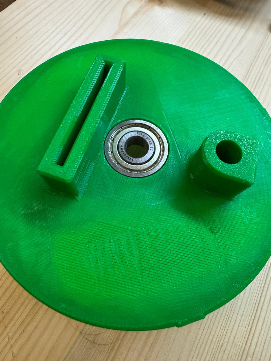
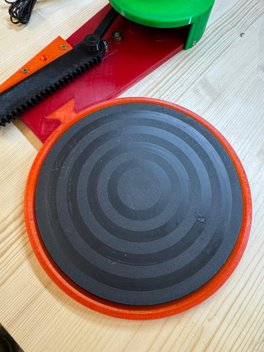
  1. 1Install centering: Attach the 3D-printed centering segments to the turntable (Figure 9.1).
  2. 2Insert turntable: Place the geared turntable into the round recess in the base plate (Figure 9.2).
  3. 3Check gear mesh: Ensure the gear is correctly oriented and meshes centrally with the rack (Figure 9.3).
✓ Verification check: The gear ring and rack mesh cleanly with each other, without colliding at the endpoints of the crank stroke.

Ready to Dissolve · Commissioning

Place the pot in the center.
Check free movement.

After completing the mechanical assembly, the station is commissioned in stages. Always perform the initial test run dry and at the lowest motor voltage (3 V).

  • 1 Dry test without a pot: Start the motor at 3 V and check whether the rack and turntable run smoothly through a full 360° crankshaft rotation.
  • 2 Center the Weck lid on the jar: Place the stainless steel container in the center of the turntable centering device to prevent tipping and lateral forces.
  • 3 Secure cable clearance: Route the slow cooker’s 230 V power cable with enough slack so that it does not become taut during rocking.
Place the pot in the center.
Ready-to-use DIY Dissolving Station with top-mounted Weck WAT24

Binding Protection & Safety Instructions

The combination of a hot water bath of up to 100 °C, 230 V mains voltage, and open drive kinematics requires the following safety precautions during operation:

230 V & Liquid

Splash-proof protection & GFCI/RCD

All electrical components (230 V connection of the pot and power supply of the grill motor) must be protected from splashing water. Operate only via a socket protected by a residual current circuit breaker (RCD).

30–100 °C hot bath

Thermal & Chemical Protection

At temperatures up to 100 °C and in alkaline/detergent baths, there is a risk of scalding. Wear heat- and chemical-resistant gloves and safety goggles when immersing and removing 3D-printed parts.

Open Mechanics

Keep pinch points clear

The rack, gear ring and crank drive have exposed moving parts. Never reach under the housing or into the gears while the motor is running; leave the motor cover fitted.

Technical Data & Compatibility

Technical specifications at a glance

System specifications for the overall setup and supported soluble support filaments.

Installation space & dimensions600 × 550 × 550 mmOverall external dimensions (W × D × H)
Heating system1,800 WHeating power at 230 V / 50 Hz (30–100 °C)
Turntable baseØ 200 mmPhoto turntable with 3D-printed gear ring
XIONEER SupportVXL 70 – 150Compatible with VXL 70, VXL 90, VXL 111, VXL 130, VXL 150
Alkali SupportSR30Compatible with other alkali-soluble support materials
Water-solublePVOH / PVA / BVOHIdeal for cold- and hot-water-soluble support filaments